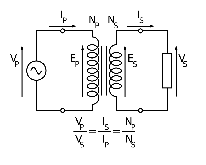
Using the model
Symbols, assumptions and limitations
The model assumes sinusoidal AC, positive whole-number winding turn counts, perfect magnetic coupling, no winding resistance, no leakage flux, no core losses, and no saturation. Voltage follows the turns ratio, current follows its inverse, and input power equals output power.
Worked examples
See the method in practice
Step-down supply
A 230 V primary with 1000 turns and a 100-turn secondary ideally produces 23 V. A 0.5 A primary corresponds to 5 A secondary current.
Step-up transformer
If the secondary has five times as many turns, its voltage is five times larger while its current is five times smaller.
Questions
Frequently asked
Why does current change inversely with voltage?
In the ideal model power is conserved. Increasing voltage by a given factor therefore decreases current by the same factor.
Does a transformer work with DC?
A steady DC current does not continuously change magnetic flux and therefore cannot sustain a secondary emf. Transformers require changing current, normally AC.
Why do real input and output powers differ?
Real transformers lose energy through winding resistance, eddy currents, magnetic hysteresis, leakage flux, and auxiliary loads.
Sources & review
Equations and examples are checked against the references below. Results are educational and should be independently verified for safety-critical work.
OpenStax University Physics — TransformersWritten by the STEM Hub editorial team · Reviewed August 11, 2026 · Review methodology